
The direction of relief displacement is different for optical and radar systems. A camera sees the relief displaced away from the nadir point while the SAR see the relief displaced towards the nadir line. This is illustrated in Figure 13.
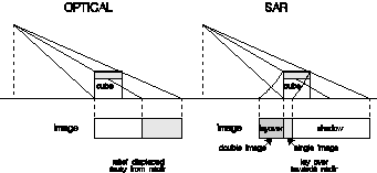
Figure 13. A comparison of relief displacement for (a) optical and (b) SAR systems.
The other effect of vertical structures is to produce shadows in the SAR image. Figures 12 and 13 illustrate this effect quite well. Because the radar beam is at an angle, there will be a region of ground behind the vertical structure that the beam cannot reach. Thus for the time period corresponding to that ground area, no echoes will be returned. This results in a black area on the image which is called a shadow. From Figure 12, the length of the shadow is calculated as

in ground range presentation and

in slant range presentation. Thus the length of the shadow is proportional to the height of the vertical structure and increases the further away that structure is from the nadir line or the lower the SAR antenna is.
The
effects of imaging sloping terrain with radar are illustrated in Figure
14. Due to the vertical height, relief displacement, lay over and
shadows can result, depending on the steepness of the slope. Slopes
facing the nadir line can exhibit the effects of (a) lay over, (c)
foreshortening and the in-between case (b) for which the front slope
appears only as a line. Case (b) only occurs when the slope is parallel
to the nadir line and the elevation angle  equals the slope angle
  exactly.
Slopes facing away from the nadir line can be (a) fully imaged, (c) hidden in the radar shadow or (b) strangely imaged as the radar beam just skims along the surface. For case (b), slight irregularities on the slope's surface would have magnified effects. For instance, a bump near the peak would block the radar from the rest of the slope causing a shadow to appear in the image.
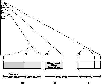
Figure 14. Image effects produced by sloping terrain.
All of these slope effects can be found in Figure 15--a subsection of the SAR image 82LWERS1 ( ESA) from the ERS-1 satellite, provided with EarthView.
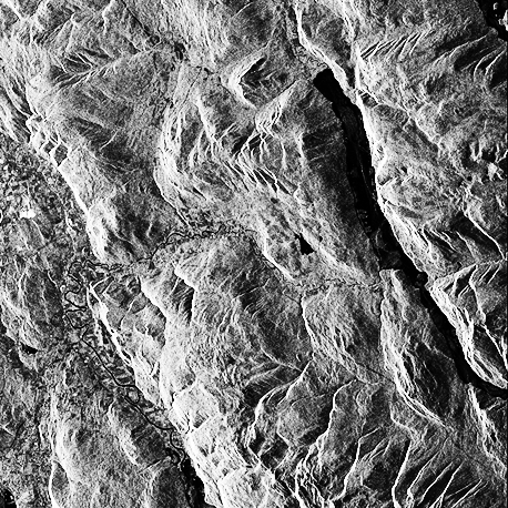
Figure 15. ERS-1 SAR image illustrating the effects of uneven terrain ( ESA).
When
an electromagnetic wave reflects off a surface, three basic properties
of the surface come into play--the dielectric constant (or permittivity  ), the roughness (rms height relative to a smooth surface) and the local slope.
Assuming that the EM wave is traveling through a medium that is homogeneous (properties do not vary from point to point), isotropic (properties are the same in all directions from any given point) and non-magnetic, then from Maxwell's equations we can express the complex electric field vector as

where A is the amplitude vector, z is the distance traveled in time t and  is a phase offset. The angular frequency
  is
is

where fc is the carrier frequency (the frequency emitted from the antenna) and  is the wavelength. The expression for k' is

where k is the wavenumber and r is the relative permittivity (also called the dielectric constant) of the medium (r = / 0 where is the permittivity of the medium and 0 is the permittivity of free space). It should be noted that r is a function of the frequency of the EM wave. The relative permeability  r has been assumed to be equal to 1 which is accurate enough for microwave frequencies.
The polarization of the electric field E is the direction of the amplitude vector A at some instant in time. For a linearly polarized wave, the direction of A is fixed in one plane relative to the direction of propagation. An elliptically polarized wave has an electric field consisting of two different components oriented along orthogonal axes such that

resulting in the total amplitude vector A slowly rotating about the z-axis. If Ax = Ay and [1 - 2] =  /2, then the wave becomes circularly polarized.
An EM wave interacting with a surface is called scattering. There are two types—surface scattering and volume scattering. Surface scattering occurs at the interface between two different homogeneous media such as the atmosphere and the Earth's surface. Volume scattering is the result of interaction with particles within a non-homogeneous medium.
A smooth surface acts as a mirror, reflecting the EM wave at an angle equal and opposite to the incidence angle  .
Thus a smooth level surface is seen as black in the SAR image since the
echoes never reach the antenna. The Rayleigh criterion defines a
surface as smooth if
.
Thus a smooth level surface is seen as black in the SAR image since the
echoes never reach the antenna. The Rayleigh criterion defines a
surface as smooth if

where h is the surface roughness, defined as the root-mean-square (rms) height relative to a perfectly smooth surface, is the wavelength of the wave and is the angle of incidence. Peake and Oliver (1971) modified this criterion by defining upper and lower values of h for surfaces of intermediate roughness to obtain a smoothness criterion of

Using the Rayleigh criterion, for instance, when RADARSAT is operating at 5.3 GHz with an incidence angle of 50o, level terrain with h < 9 mm will show up as solid black.
Any returns from a smooth level surface are due to specular scattering, in which the EM wave's angle of incidence is equal and opposite to the angle of reflection and the transmission through the surface obeys Snell's Law