
March 13, 2019
David W. Porterfield, Jr., Micro Harmonics Corp., Fincastle, Va.
Isolators are non-reciprocal devices, passing electromagnetic (EM) signals in one direction and absorbing them in the reverse direction. They are primarily used to suppress standing waves that arise due to impedance mismatches between highly-tuned components, such as those found in frequency multiplier chains. Standing waves cause dips - even nulls - in the output of the multiplier chain. They can be mitigated by inserting isolators between the multipliers, resulting in a much smoother frequency response and improved bandwidth.
Traditional Faraday rotation isolators provide greater than 20 dB of isolation over full waveguide bands, with some exceeding 30 dB. While there are more than a dozen vendors worldwide, the design has largely remained static since the 1970s. Insertion loss is low in the microwave bands, steadily increasing with frequency. At mmWave frequencies, the insertion loss becomes problematic: in the WR10 band (75 to 110 GHz), insertion loss can exceed 3 dB; in the WR3.4 band (220 to 330 GHz), the loss can be greater than 7 dB, making the isolators impractical. There are few suppliers in the bands above 110 GHz; isolators for the WR4.3 and WR3.4 bands, produced many years ago, are now difficult to find. At these frequencies, the constituent parts are very small, difficult to fabricate and align - and with more than 7 dB insertion loss, there is not much demand.
In 2001, Erickson1 demonstrated that insertion loss can be dramatically reduced. Yet, for many years following that work, very little changed in the commercial market. In 2015, with funding from NASA JPL, Micro Harmonics Corp. developed a line of mmWave isolators designed for low insertion loss. These isolators have a typical insertion loss of less than 1 dB in the WR10 band and about 2 dB in the WR3.4 band. These numbers are game changers, and mmWave system developers are reconsidering their use. Micro Harmonics is currently the only worldwide producer of full band, low loss isolators in the WR4.3 (170 to 260 GHz) and WR3.4 (220 to 330 GHz) bands, and is developing designs for the WR2.8 (265 to 400 GHz) and WR2.2 (330 to 500 GHz) bands.
FARADAY ROTATION ISOLATOR THEORY
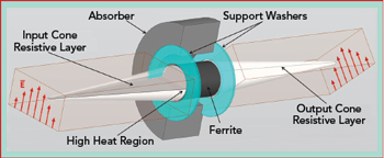
Figure 1 Structure of a Faraday rotation isolator.
At frequencies from 50 to 330 GHz, the dominant isolator topology is Faraday rotation with transitions to rectangular waveguide, as described by Barnes2 in 1961. At the heart of the isolator are a cylindrical ferrite core and a pair of alumina cones bisected on their central axes by resistive layers (see Figure 1). For improved visibility, the absorber is shown split in half, with the top half of the input cone semi-transparent. The cones couple the dominant TE10 waveguide mode to the HE11 hybrid dielectric mode in the ferrite. The ferrite and cones are suspended in the waveguide structure by a pair of washer-shaped supports. The output cone and waveguide are rotated 45 degrees with respect to the input cone and waveguide. An absorber is used to suppress higher-order modes near the ferrite core.
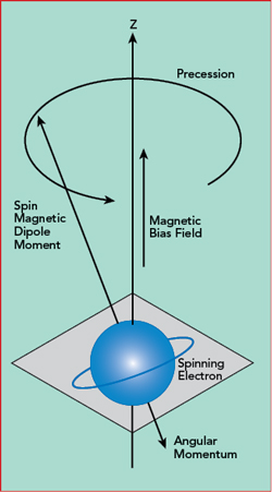
Figure 2 Spinning electron angular momentum and spin magnetic dipole moment vectors.
The E-field in the TE10 mode is normal to the resistive layer in the input waveguide. The field is rotated 45 degrees counterclockwise as it passes through the ferrite and emerges normal to the resistive layer in the output cone. No currents are generated in either resistive layer by the forward traveling wave, and there is no associated loss. The direction of rotation is the same for both the forward and reverse waves, giving rise to the non-reciprocal nature of the device. The reverse traveling wave is rotated into the input cone resistive layer and absorbed, i.e., converted to heat energy.
All materials have electron spin states which create magnetic dipoles. In non-magnetic materials, the dipoles are randomly aligned, and there is no net magnetic dipole moment. In ferrite materials, some of the magnetic dipole moments can be aligned. Application of a DC magnetic bias field causes additional dipoles to align, and the magnetic moment increases. Further increases in the magnetic bias field give rise to larger net magnetic dipole moments until a point of saturation, beyond which further increases in the bias field produce no change. This condition is referred to as magnetic saturation. The magnitude of the saturation magnetization (4πMs) is a material property in the range of 300 to 5000 G for most commercial ferrites.
The magnetic dipoles precess around the magnetic bias field vector (see Figure 2). As an EM signal passes through the ferrite, the fields interact with the dipole moments. Linearly polarized waves, like those passing through the isolator, can be decomposed into left hand and right hand circularly polarized waves, LHCP and RHCP, respectively. The interaction with the precessing dipole moments results in disparate propagation constants for the RHCP and LHCP waves. The difference in the propagation constants is because one of the components (RHCP or LHCP) opposes the dipole precession and the other coincides. A phase shift occurs between the RHCP and LHCP waves as they travel through the ferrite, resulting in the rotation of the linearly polarized signal. A more in-depth discussion of Faraday rotation is given by Pozar,3 Lax et al.4 and Balanis.5
SIMULATIONS
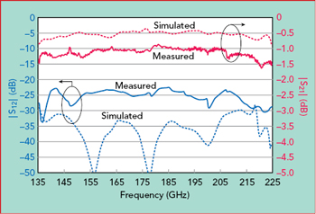
Figure 3 Simulated vs. measured insertion loss and isolation of a WR5.1 isolator.
HFSS6 is used to model and simulate isolator performance. The final models contain all relevant parts, including the core region surrounding the ferrite, the waveguides and twist steps. The simulations include the Faraday rotation effect using a magnetically biased ferrite, as well as ferrite dielectric loss and waveguide conductor losses.
Figure 3 compares the simulation and measured data for a Micro Harmonics WR5.1 isolator. The standard WR5.1 band is from 140 to 220 GHz, and the data in the figure covers an extended range from 135 to 225 GHz. The simulated insertion loss is about 0.5 dB lower than the measured data. The discrepancy is likely due to small misalignments in the assemblies and under-estimation of waveguide conductor loss in the models. The discrepancy between simulated and measured isolation (i.e., |S12|) is also attributed to small alignment and fabrication errors in the constituent parts. Very little data is available on the material parameters at these frequencies, also contributing to model inaccuracies. Qualitatively, the data are in good agreement, and the measured insertion loss is much better than the typical insertion loss of old-style isolators, which was greater than 4 dB in this band.
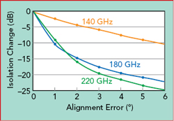
Figure 4 Isolation sensitivity to rotational misalignment of the input cone.
HFSS simulations on the WR5.1 isolator model illustrate the sensitivity to alignment and fabrication errors. Incrementally rotating the input cone out of alignment, while every other part is held in perfect alignment, degrades isolation by approximately 10 dB for a 1 degree alignment error at the center and upper end of the WR5.1 band (see Figure 4). A fabrication error of only ±0.001 in. in ferrite length also causes a 1 degree rotational error, with similar results.
There are challenges to fabricating and assembling mmWave isolators. The constituent parts are tiny and, as illustrated, small alignment errors can significantly degrade performance. Misalignment can also increase coupling to higher-order modes in the region near the ferrite core, resulting in unwanted structures in the response. The assembly process is an art, and no two isolators have the same signature, motivating continual efforts to improve the uniformity of the assemblies. Every isolator is thoroughly tested on a vector network analyzer to ensure conformity with specifications.
MINIMIZING LOSS
Two of the largest contributing factors to insertion loss at mmWave frequencies are loss in the ferrite and waveguide conductor loss.
Minimizing Ferrite Loss
The EM field rotation in a Faraday rotation isolator is described by the equation

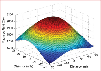
Figure 5 Measured magnetic bias field near the surface of the ferrite. The maximum field is 2056 Oe.
where 4πMz is the axial magnetization, Υ is the gyromagnetic ratio (8.795 x 10⁶ x g rad/s/Oe), l is the ferrite length, c is the speed of light and ε is the ferrite dielectric constant. This equation shows that field rotation is directly proportional to ferrite length and axial magnetization. Minimum insertion loss and maximum isolation occur when the EM field is rotated by 45 degrees as it passes through the ferrite. Ferrites are lossy at mmWave frequencies, so it is essential that the length be reduced as much as possible.
近日,電子科技大學自動化工程學院研究團隊在期刊《神經網絡》上發表研究性論文。該文首次提出毫米波近場透視成像與可見光的圖像融合方法。隨著目標檢測技術的快速發展,多種傳感器在提升檢測精度方面發揮著關鍵作用......
現代信息社會中,移動通信是實現信息高效流動的基本手段。近期,第五代移動通信系統(5G)已實現大規模商用。當前,5G長期演進和第六代移動通信系統(6G)成為學術界和產業界的研究熱點。實現高通量無線通信的......
毫米波(名詞解釋?)與太赫茲波(名詞解釋?)探測技術在通信、安全、生物檢測、頻譜分析等領域有著廣泛的應用。它們是將承載著毫米波與太赫茲波的光信息轉變為電信號的核心技術。高靈敏度、寬波段、快速響應及面陣......
近日,由中國科學院沈陽自動化研究所團隊與以色列魏茨曼科學院(WeizmannInstituteofScience)研究團隊,聯合提出了針對多輸入多輸出(Multiple-InputMultiple-O......
在時間某處,也許就是此刻新一代的技術變革正激發全新理念的誕生作為未來科技的推動者我們幫助從事前沿研究的高校、公司、研究機構,開啟測量新視野使其產品從概念到商用,速度更快科技的迅猛發展帶來了很多新的變化......
今日推薦文章作者為東南大學毫米波國家重點實驗室主任、IEEEFellow著名毫米波專家洪偉教授,本文選自《毫米波與太赫茲技術》,發表于《中國科學:信息科學》2016年第46卷第8期——《信息科學與技術......
對于投資者來說,軍民融合一直是雙創中一個重要的領域,由高校實驗室走出的項目往往具有高精尖等特點。但是另一方面,這些項目往往都是軍轉民,而且項目長期處于高校之中難以發現。為了提高科技成果轉化,支撐產業發......
由北京航空航天大學承擔的“新能源汽車”重點專項“電動汽車智能輔助駕駛關鍵技術研究與產品開發”項目“智能輔助駕駛環境感知關鍵技術研究與產品開發”課題研究取得階段性成果。課題重點圍繞77GHz毫米波雷達關......
分析測試百科網訊2017年2月23日,國家重大科學儀器設備開發專項“毫米波成像探測儀研制及產業化示范”項目(2012YQ140037)初步驗收會在同方威視密云基地召開。國家科技部資源配置司副司長吳學梯......
意大利電信近日宣布成立一個毫米波(mmWave)頻段實驗室,用于研究毫米波在5G網絡中的應用。意大利電信是歐洲第一家開設毫米波實驗室的電信運營商。這個位于都靈的實驗室包括遠場緊湊天線測試系統和球面近場......