UE Placement in Test Setup (Antenna Distance between UE and Test equipment)
In order to get a repeatble, reliable and stable measurement result, it is very important to place the AUT(Antenna Under Test) and the measurement antenna in proper position. In this section, I will explain on how to determine the proper antenna position and theoretical background on why the specific posiiton should be used.
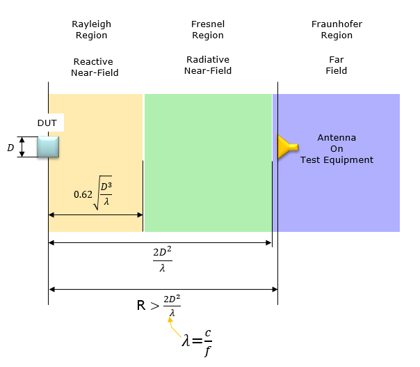
Minimum far-field distance R for a traditional far field anechoic chamber are determined by the formula a shown below (Based on R5-180013).
< Figure 1 : Antenna Field Region >
The near/far field boundary for different antenna sizes and frequencies is shown in the table below. This table is based on R5-180013 (Ref [1]) - Table 2.2.1: Near field/far field boundary for different frequencies and antenna sizes for a traditional far field anechoic chamber
< Table 1 - Near/Far Boundary distance with D and Frequency >
D(cm) | Freq(Ghz) |
| Near/Far Boundary (cm) | Path Loss |
5 | 28 | 47 | 48 | 55 |
10 | 28 | 187 | 188 | 66.9 |
15 | 28 | 420 | 420 | 73.8 |
20 | 28 | 747 | 748 | 78.9 |
25 | 28 | 1167 | 1168 | 82.7 |
30 | 28 | 1680 | 1680 | 85.9 |
5 | 100 | 167 | 168 | 76.9 |
10 | 100 | 667 | 668 | 88.9 |
15 | 100 | 1500 | 1500 | 96 |
20 | 100 | 2667 | 2668 | 101 |
25 | 100 | 4167 | 4168 | 104.8 |
30 | 100 | 6000 | 6000 | 108 |
NOTE : From this is the optional reading. I've looked into the equation a little bit deeply just out of curiosity. If may skip this part if you are not interested. I tried to investigate on how the near / far boundaries changes as frequency changes.
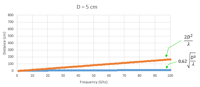
As shown below, the span of Radiative Near Field (the gap between the end of Reactive Near Field and the Start of Far Field) gets drastically increases as frequency increases where as Reactive Near Field distance relatively slowly increases). Also, comparing the following two plots, you would notice that the Far Field distance gets drastically larger as D increases.
< Figure 2 - Field Boundary change with frequencies at D = 5 cm >
< Figure 3 - Field Boundary change with frequencies at D = 10 cm >
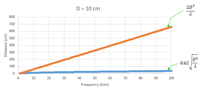
Now you may have an interesting question. According to the plots shown above, the distance between DUT antenna and equipment antenna should increase as frequency increases. That is, the size of Anechoic chamber should increases as frequency increases ? Isn't it counter intuitive to you ? Our common sense (our RF intuition) says the size of frequency dependent object tend to decrease as frequency increases.
How do we handle this conflict with our intuition and the plots show above ?
The solution lies in the fact that D is not a constant in realilty. In case of plots shown above, D has a fixed value regardless of frequency. But when we design an antenna, we usually decide D value(Antenna Aperture size) in terms wavelenth as shown below. Here, k is just a constant like 0.5, 1, 2 etc.

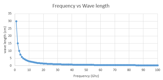
If you plot on how wavelength (lamda) changes as frequency increases, you will get a plot as shown below. You will notice that the wavelength decrease dtrastically.
< Figure 4 - Wavelength vs Freuqnecy >
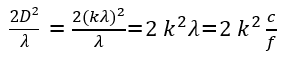
If you rewrite Far Field distance equation, it becomes as shown below. In this equation, you will notice that the Far Field distance decreases as frequency increases. (NOTE : if you want to try calculate in real value, take f as 'frequency in Hz' and c as 'the speed of light in m', k is just a constant without any unit).